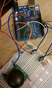
For our PComp HW this week, the assignment was to learn how to use a potentiometer, photo-resister, and joystick, and then make something cool.
I started by testing a potentiometer using this tutorial code. One side is connected to 5V, the other side is connected to ground. The middle pin is connected to Analog-In pin 2. As the dial turns closer to the side connected to 5V, more power is sent toward Analog-In and the LED on pin 13 blinks faster. As the dial turns closer to the side connect to ground, less power is sent toward Analog-In and the LED on pin 12 blinks slower.
Potentiometer from Tami on Vimeo.
Next, I experimented with a photocell using this example code. I was able to see that the photo-resistor affects the resistance based on the amount of light shining onto the cell.
Next, I tweaked this example code to see how a joystick works.
Using an RGB LED, I wanted to control the colors emitted from the LED using the joystick. I used the map function to map the joystick position values (0 to 1023) read by the Analog pins on the Arduino to values that are relevant for the RGB colors of the LED (0 to 255). I then assigned these mapped values to each of the R, G, and B pins of the LED. Here is the code I generated for this function, and a video following.
Joystick + Color from Tami on Vimeo.
Finally, I attached another RGB LED to my board and altered the code to have this second LED light exactly opposite as the first. Now the LEDs light with complementary (opposite colors).
Here is a picture of my circuit…

…and video of it in action. (Sorry it is hard to see due to the brightness of the LEDs and video quality)
Joystick + 2LEDs from Tami on Vimeo.
Don’t forget to check out my FINAL CODE.